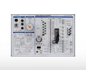
ㆍStudy features and principles of DC Servo Motor
ㆍLocation decision experiment by linear guide and TM screw
ㆍSpeed and location control
ㆍMotor control by PWM
ㆍDigital display of motor speed and moving distance
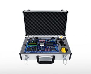
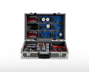
Specifications
A. DC Power Supply
– Power for Servo motor
– Output voltage ±15V
B. Attenuation
– 100kΩ potention meter(10turn) : 1ea
– 100kΩ VR : 2ea
C. Summing Amplifier
– Negative AMP
– Input : 3ea
D. Pre-Amplifier
– OP AMP
– GAIN ADJ by VR
E. Motor Drive Amplifier
– Differential amplifier to operate Servo motor
– Overload protection circuit
– “+”, “-” Differential Input circuit
F. F/V Converter
– Polarity convert
– Input : Phase A, Phase B
– CW, CCW Display (LED)
– Output : DC ±0V ~ 10V
G. Servo motor
– DC 12V
– Reducer
H. Integrator
– Integration to control PI
– Output ±12V
– RC intergrator circuit by OP AMP
I. RPM Meter & mm METER
– Rotation number and moving distance Display by switch
– 3 digits, 7 segments, FND indicator
J. Function generator
– Triangle wave and square wave Output
K. Location decision device
– Linear guide
– TM Screw & Nut
– LIMIT switch
– Max. moving distance: More than 100mm
L. Location detection
– Potention Meter(10turn) : 1ea
– Reduction device
M. Rotary Encoder
– Output Phase A, B, Z
– Resolution : 200P/R
– Output Totem Pole
– Max. response frequency : 180kHz
N. Digital Volt Meter
– 3 digits, 7 segments, FND indicator
– Input range : DC ±0 ~ 99.9[V]
– Resolution: 0.1[V]
O. POWER
– AC 220[V], 50/60[Hz]
– Power switch
– Emergency switch


![[:vi]Bộ đào tạo động cơ servo DC - CPE-ER190[:en]DC Servo Morot Trainer CPE-ER190[:]](https://amescovn.com/wp-content/uploads/2024/08/cpe_er190.jpg)
 Gọi điện
 SMS
SMS Chỉ Đường